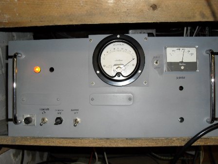

Descibed here is a power supply unit suitable for feeding linear amplifiers using 4CX250B's. Most of the componets came from the junk box so there is plenty of scope for component substitution. Rails provided by this PSU are ;
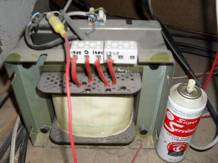
Interlock time delays are used on the HT and Screen supplies so these are only active once the heater supply has been present for 2 minutes. HT is derived from a 1.8 KW continous duty transformer with a seconary voltage of 1600 VAC, more about this later as there are several other transformers that can be used without spending much money. The 1600VAC is full wave rectified and then fed through a pie filter, this arrangement is used as there were sufficient electrolytics and a large smoothing choke in the junk box, however, a simple reservoir capacitor bank following the bridge rectifier would also be fine here although the HT would be slightly higher, a total capacitance of 20uF of greater will be ok for a linear using two 4CX250B's. A soft start circuit is also employed in the HT circuit, without this the mains fuse to HT transformer would often blow on switch on. Screen grid supply is derived from a seperate transformer with a secondary voltage of 300 VAC approximately. Cold cathode regulator tubes are used to stabilise the screen supply and also caters for negative screen grid current which sometimes occurs depending on how hard the valve is driven, conduction angle and its condition. Several regulator circuits have been tried over the years, both thermionic and solid state, but for me, the cold cathode regulator is my first choice mainly because most of the 4CX250B's I use are not new and can flash over from the anode to the other electrodes but this is rare ( even new valves can do this ), thus putting 2100 volts down the screen regulator rail. No solid state regulator circuits tried have ever survived this occurance, but the cold cathode circuit has never failed - I guess sometimes simple is the best.
Looking at the circuit diagram you will see it is very simple. R - C time constants are used for generating the HT and screen suply time delays. HT soft start is acheived by placing a 10 ohm resistor in series with the HT transformer primary, this is removed from circuit by a relay contact closure after approximately 4 seconds. Originaly the sensing voltage for the soft start circuit was taken from the 26 VAC winding on one of the three Pye transformers, now as there are no low voltage windings on the present HT transformer a small 10 Watt 24 VAC transformer is used which sits on top of the HT transformer. HT and Screen supplies are inhibited for 2 minutes from heater switch on to avoid tube damage. It is very important that the 47 ohm wire wound resistor in series with the HT output is not omitted, its purpose it to limit any surge current due to a valve flash over or short, without it much damage will occur to both PSU / linear and a new set of underpants will be required.As an aside, in order to protect anode current meters in linear amplifiers, a 1N4007 forward biased diode across the meter and its shunt will normally keep the meter movement safe during a flash over.
Special care should be given to the 2100 volts HT part of the PSU. Note the smooting capacitor bank is well insulated from the metal chassis by use of rubber foot matt material and a perspex board ( do not rely on the thin plastic film around the capacitors ). The wires carrying HT is the inner conductor from RG58 coax. The HT sockets used on rear of the PSU are only rated for 1500 volts DC, these will be fine if first mounted on a perspex panel which is then mounted on to the chassis with a chassis cut out for the panel leaving at least a 1cm gap between the chassis and the sockets ( Although I have not done this yet, if they break down to chassis then it will be done ). An old PMR base station case is used to house the PSU, unfortunately the now larger HT transformer does not fit in the case so is left on the shack floor with RG58 inner conductor for the connecting wires. Apart from the multiple HT outlets, all other supplies are available on several Jones type sockets ( one for each linear in the shack ) mounted on the rear of the chassis. If you are experimenting with these high voltages, please be very careful, these are lethal voltages.
Barry Zarucki M0DGQ
HOME